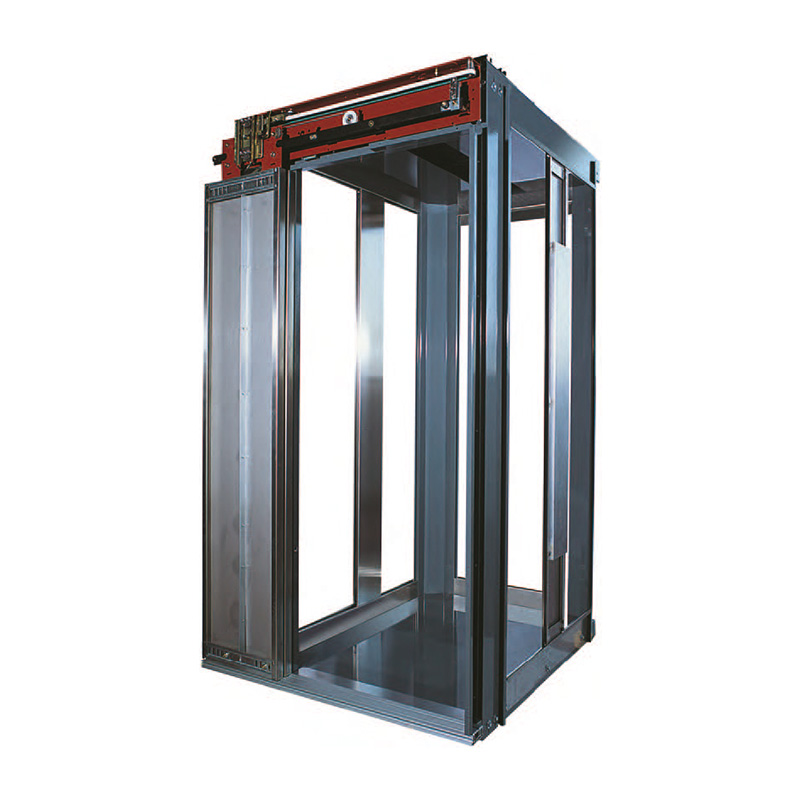
| Drive |
Hydraulic |
| Valve group |
3010 DLV |
| Machine |
GLDRY |
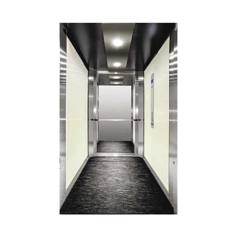
| Description |
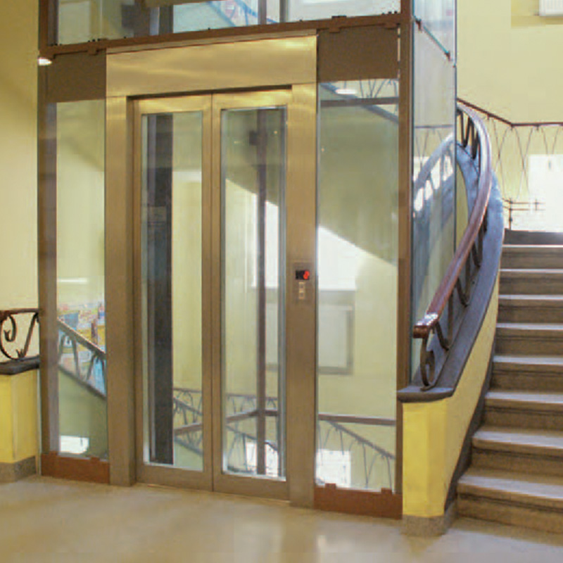
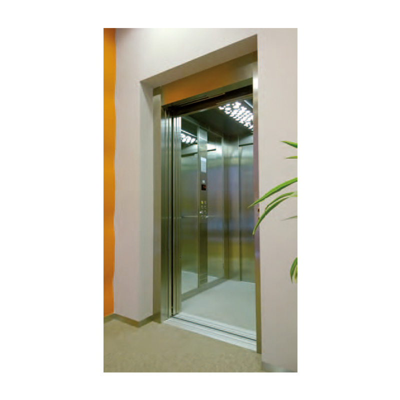
Indirect acting hydraulic lift (2:1) |
| Speed |
0,62 m/s |
| No. of stops |
2 ÷ 12 |
| Cabin tour |
19 m |
| Flight |
3300mm |
| Pit |
1000mm |
| Machine room |
Not necessary. TYPE C cabinet (L 870 x D 400x H 2100mm) |
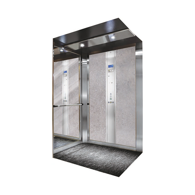
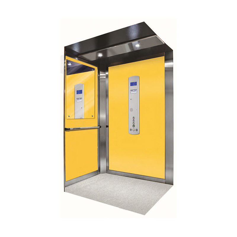
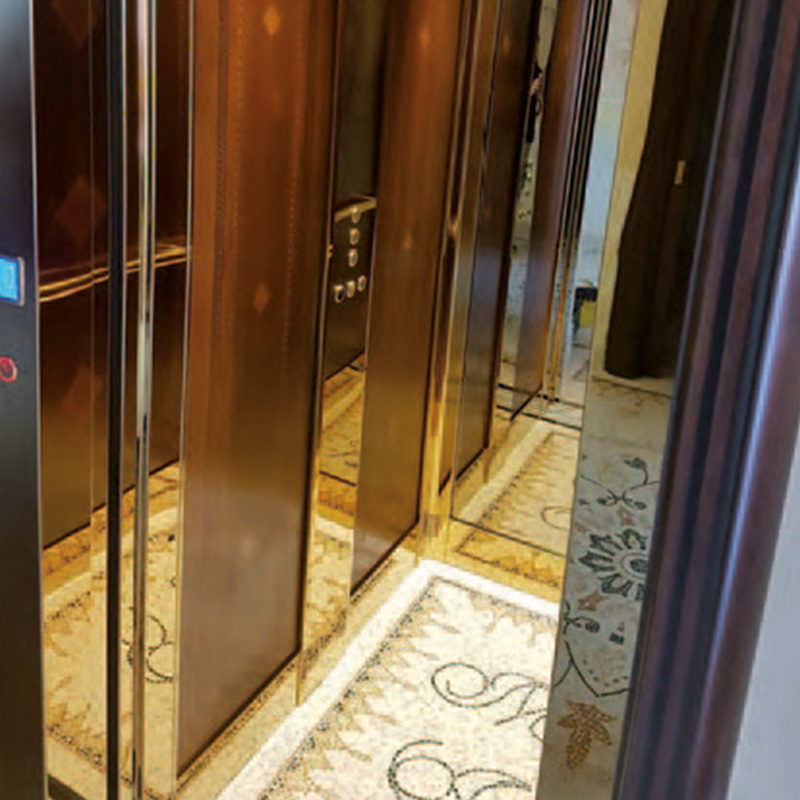
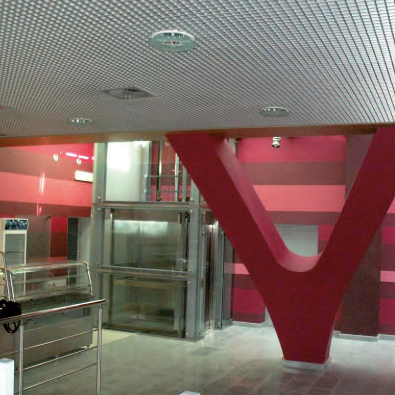
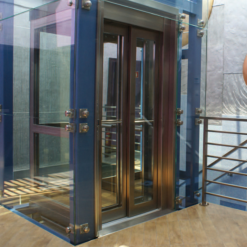
| Intended use |
Residential, office, hotels, public and private. |
| Compliance with directives and standards |
Lifts Directive 2014/33/EU; Electromagnetic Compatibility Directive 2016/30/EU.
Harmonized Standard: EN 81-20 – EN 81-50 (Safety Rules for Lifts); EN 81.28 (Elevator Remote Alarm). Optional: EN 81.70 (Elimination of architectural barriers); EN 81.58 (Fire-resistant doors); EN 81.21 (Reduced pit and/or reduced free space); EN 81.73 (Behavior of the lift in case of fire); EN 81.72 (fire-fighting lifts) with fire-fighter control |
| Safety devices |
• According to EN 81.20 it has UCM (Uncontrolled Cabin Movement)
PARACHUTE:
• INSTANT Technolift SH3 – SH4 – SH8 – SH9
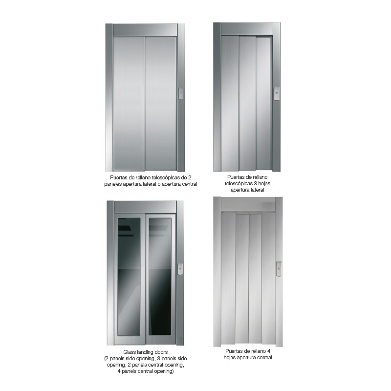
DOOR LOCKING DEVICE:
• GMV – Euro-Vip 96 0001 (2AT - 2AO with standard limit)
• GMV – Euro-Vip 05 0002 (3AT and door with reduced limit)
• Built-in door opening return |
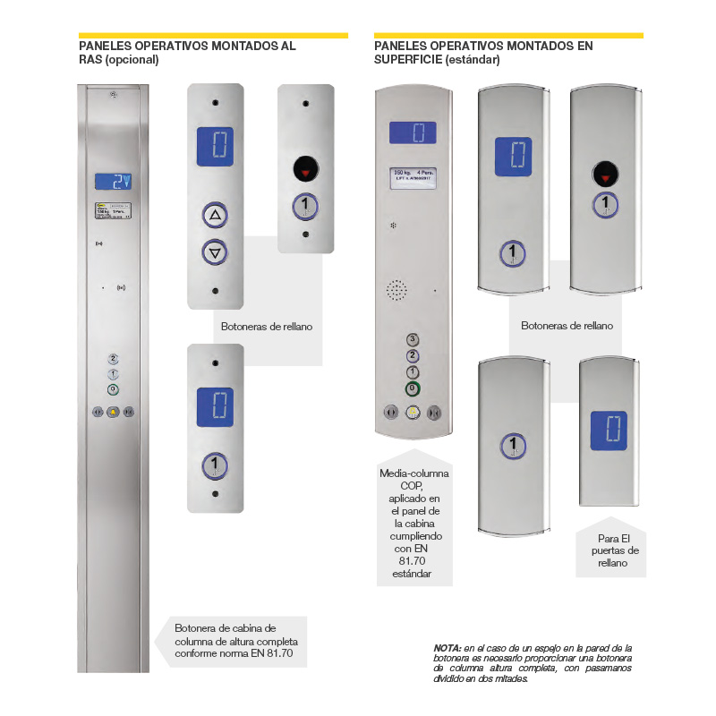
| Electrical part |
• NEOS10+ model microprocessor-based control panel
• Universal Maneuver -Collective descent- collective ascent/descent
• Emergency descent: UPS integrated into the control panel. |
| Others |
Lighting in the gap |
| Hollow type |
Reinforced concrete/bricks/metal structure |