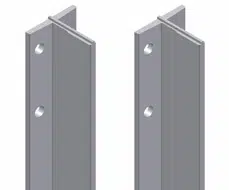
The resistance of the guides must be sufficient to withstand the loads to which they are subjected, thus guaranteeing the safety of the elevator and its passengers .
The aspects to consider for the correct functioning of the guides are:
a) Correct guidance of the cabin and the balancing mass must be ensured.
b) Deformations must be limited to ensure the following:
Unintentional unlocking of the doors must not occur.
It must not affect the operation of the safety devices.
It must not be possible for one of the moving parts to collide with another.
For the calculation of the guides, different load hypotheses must be taken into account:
Hypothesis 1: Normal functioning
The cabin is considered to be fully loaded, that is, at the maximum weight it can operate.
Hypothesis 2: Loading and unloading of the cabin
The weight of a person standing on the cabin step is taken into account, the place furthest from the centre of mass of the cabin, and which therefore causes a greater bending moment.
Hypothesis 3: Action of a security device
The guides are checked to ensure they can withstand the loads produced by the operation of a safety device that stops the cabin, causing a large deceleration. For example, the parachute valve or the chassis wedging system.
The guides must be sized taking into account the bending and buckling forces of the different hypotheses described above. In calculating the bending forces, we will assume that:
The guides are a continuous beam with flexible fixing points at a distance of 1.
The resultant of the stresses causing bending stresses act at the midpoint of two adjacent fasteners.
The bending moment acts on the neutral axis of the guide profile.
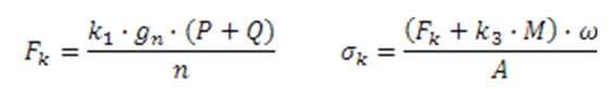
Buckling calculation
Legend: Fk is the buckling force, in N σk is the buckling force, in Newtons per square millimeter k1, k3 are the corresponding impact factors gn is the acceleration of gravity (9.81 m/s2) P is the mass of the empty cabin, in kilograms Q is the nominal load, in kilograms n is the number of guides A is the resistant area of the cross section of the guide, in square millimeters ω is the value of omega, referring to the slenderness of the guide
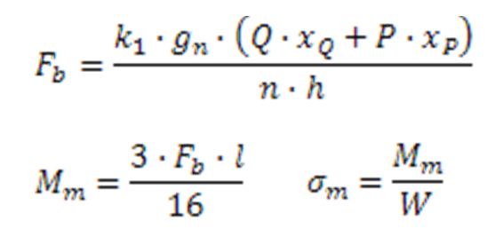
Bending calculation
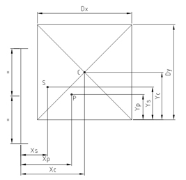
Legend: k1 is the corresponding impact factor gn is the acceleration of gravity (9.81 m/s2) P is the mass of the empty cabin, in kilograms Q is the nominal load, in kilograms xQ / yq is the distance from the cabin mass (P) to the guides xp / y q is the distance from the nominal load (Q) to the guides n is the number of guides h is the distance between cabin guides Fb is the force applied to the guides, in newtons l is the maximum distance between guide fixings, in millimeters Mm is the bending moment, in newtons millimeter Wy is the resistant moment of the cross section, in square millimeters σy is the bending stress, in newtons per square millimeter
Bending stresses must be calculated on both the abscissa and ordinate axes in order to perform a proper calculation. Subsequently, the stress combination must be carried out according to EN 81.2, and it must be verified that these do not exceed the admissible stress of the guide material.
In this way, the guides that allow the movement of the cabin ensure safety in any situation that may occur during the operation of an elevator.


One Response